a tour of version 2.0
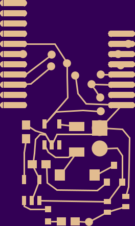
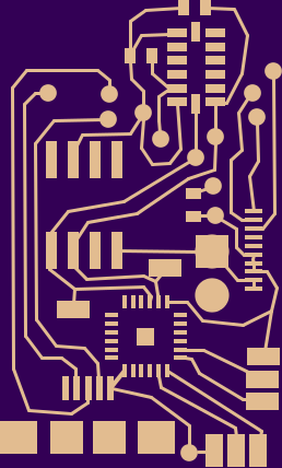
So, after many weeks slaving at the computer every night, I’ve managed to produce a circut board design for v2 of the watch. The design is a little rough around the edges, but I think it’s worth walking through things at this point. First, some general considerations: I decided not to give a shit about cost per component in this design. I’m working with a lot of other constraints, mainly board speace, my time, and my ignorance. So almost all of these components are things that I’ve seen used in kits, things that are dead simple, and usually the smallest available version. Where possible, I’ll link to resources that have helped me along the way. The software that I ended up using was the one with the easiest learning curve, Fritzing . The biggest drawback is that it can only do 2-layer boards. I could probably make the board 20% smaller with a four layer design, but I’m unwilling to pay for eagle, and KiCAD was impossible to install when I was trying. I did later get a binary version to work, but the drag-and-drop simplicity of Fritzing sold me.
The heart of this board is the RFduino, a mostly Arduino compatible ARM M0 system-on-chip with 7 GPIOs that runs at 3V. It was chosen for it’s size and ease of programming; there are a ton of libs and code that work out of the box for it. Also, it’s very small; smaller than a microduino, and has blutooth built in. It was suggested to me by my friend @mojinations . Originally, I was going to do something very similar to the OSWatch, just build the Amtel and the bluetooth into the same board. When I found the RFduino, I knew it was the right part, just based on size alone. The drawback being that it’s SMT only, which has made prototyping interesting, to say the least. Also, it only exposes 7 of the processor’s available 30-some GPIOs. I understand there’s a space constraint, but it would still be nice to have a few more (not to mention reducing my part count and complexity even further).
Moving on to power, I’m using a lipo battery like this one from Adafruit. This feeds a Maxim MAX1724EZK30 regulator, which was chosen for its very low quiescent current, although it was a bit more costly than other switching regulators.The board also will charge the battery over USB. It uses a MCP73831 charging IC and a power sharing circut described here ; basically it uses a MOSFET transistor to switch to the USB power when it’s connected. As an aside, I found that page looking at photos of other people’s DIY watches. His is pretty rad.
Next is the screen. Sharp makes a family of low-power memory displays, which are like e-paper, but with fast refresh rates. I decided to build around one of these instead of a more typical OLED because I always want the display to be on, telling the time. If a watch is about displaying essential information, it shouldn’t need a button press to see it. I got the idea from the Adafruit breakout board, which isessentially a level shifter and a voltage regulator hooked directly to the screen. There are actually two displays that are interchangeable here; one 96×96 and one 128×128. They’re physically about 1mm different, and the connector is the same. Unfortunately, they’re also backordered everywhere; I’ve been forced to buy breakout boards to get the part.
On the I2C bus, we have three chips. First there’s an accelerometer, which I have no idea if it’s the right one, but it’s at least widely supported. This will allow the watch to do activity tracking and shake gestures. Second is the real time clock. I went with the Maxim DS3231MZ+, which has an internal oscillator, so reduces the BOM by 1 part. I could probably get away without a RTC, I mean, my current version doesn’t have one. That said, it’s pretty essential that the watch keep time. Last on the I2C bus is a I/O expander, which has 4 pads exposed for buttons, and another two for shits and giggles. I should probably make the extra two pads the I2C bus.
The full BOM is in this google doc . There are some various capacitors, resistors, and such that do things like power conditioning, pullups, or config. Nothing super crazy. The full set of gerbers is in the github repo, along with the code I’m currently using. Astute readers will note that none of the new hardware is implemented at all yet. It’s on my todo list, as soon as I build it.
Posted by Matt on 2014-07-10 15:58:50 +0000