Desoldering braid is magic (or, Building prototypes is hard)
So, to kill any suspense that may have been building over the last couple weeks, I’ve managed to complete a first prototype of my open watch. As it turns out, a lot of people have built these over the last couple years, as hobby parts get more sophisticated and smaller. It’s now possible to take a bunch of off the shelf stuff and build a smart watch in any number of configurations. It’s not long before you can build a phone, similarly.
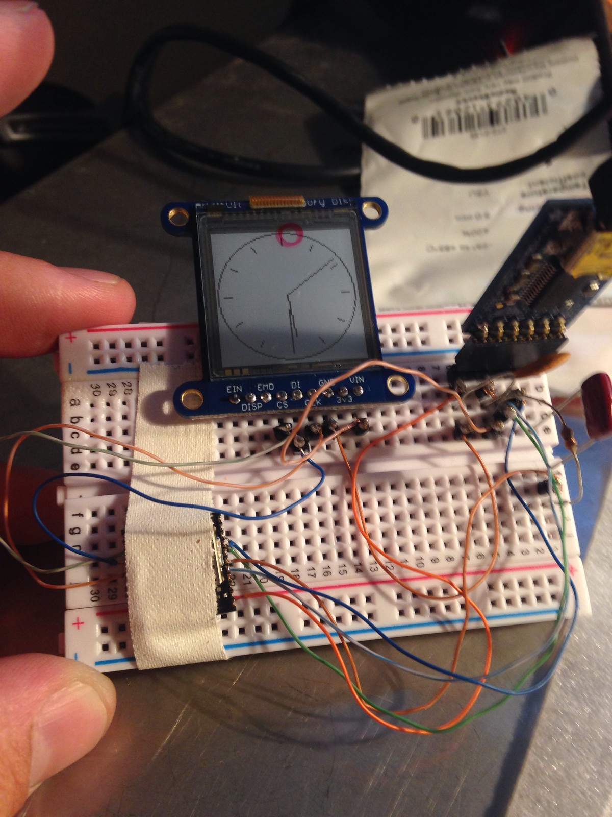
I hesitate to go into too much detail. There’s a lot of this that’s arbitrary, or an accident of me painting myself into some corner through mistakes early on, or simply unexamined. I’m sure there are several lucky breaks I don’t know about, in addition things like the fact that the display breakout I’m using has a voltage regulator. You can see from the photos that it took a lot of working and re-working. What I’d like to do is to teach the knack that helped me know where to look for problems when they came up. How to work through a decision tree of what parts to use, where, and when, what connections to make,
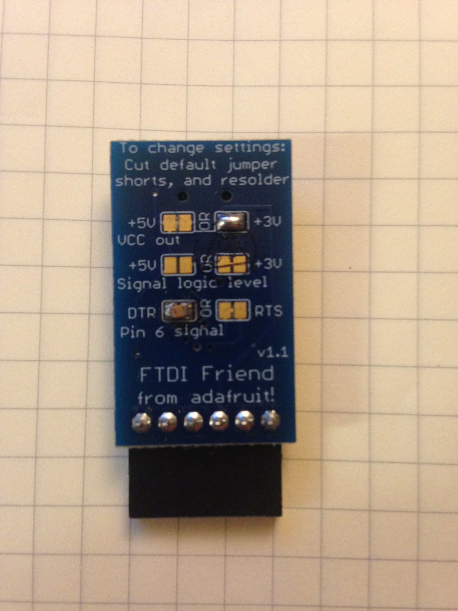
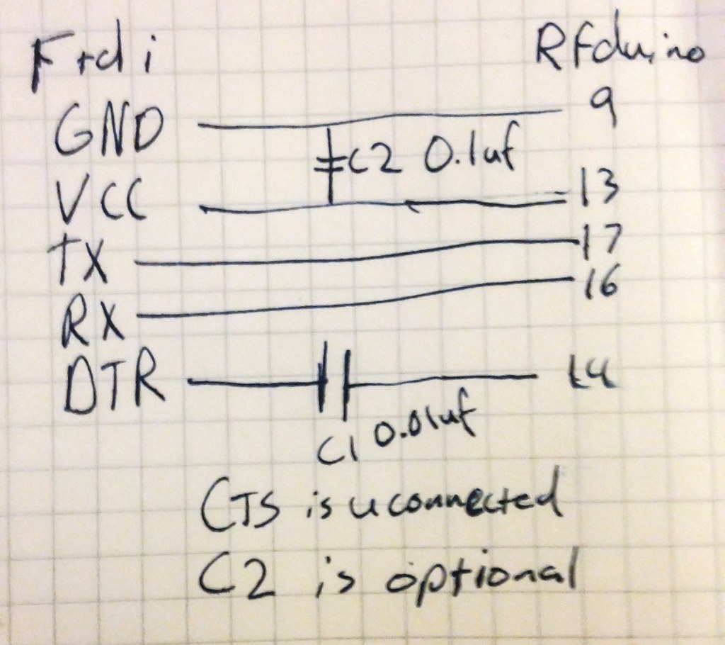
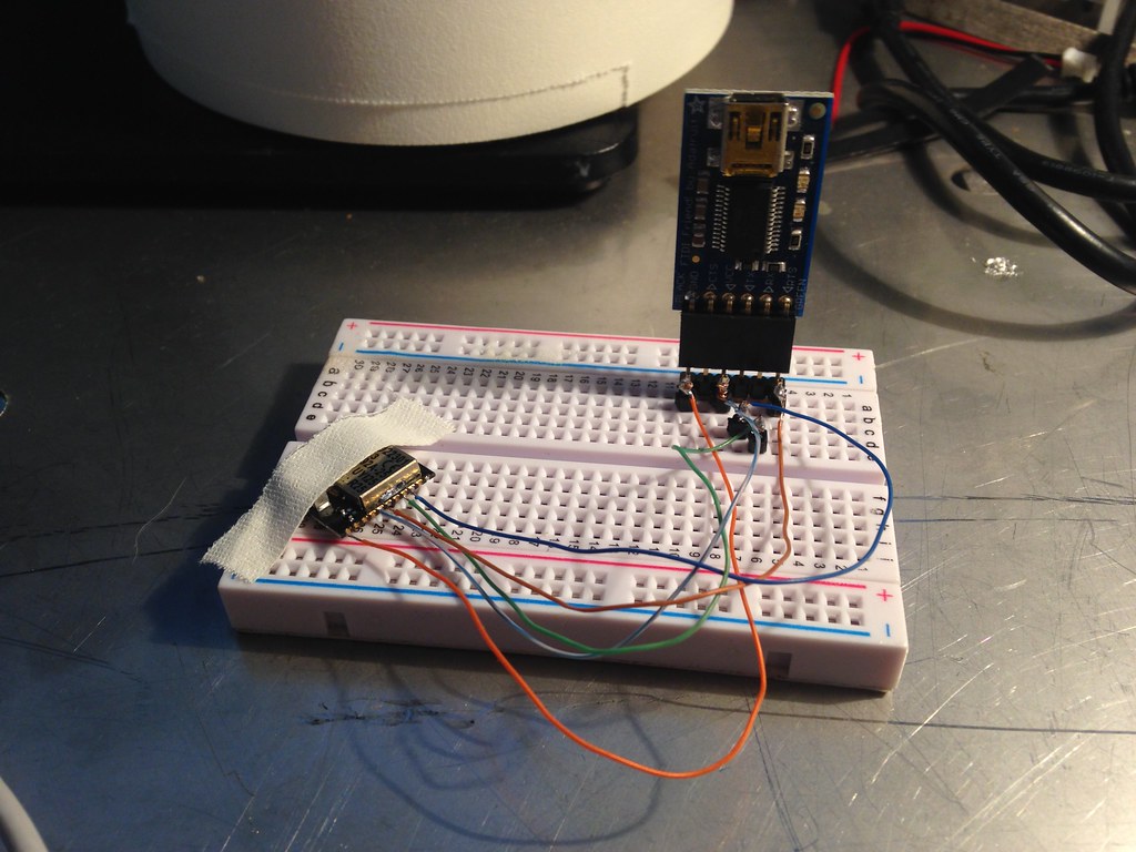
As hinted in an earlier post, the heart of the beast is an RFduino, an Arduino compatible ARM and Bluetooth LE system on chip (SoC). The prototype is built on an an Adafruit perma-proto, but you could proably use any standard perf board. The display is this one, which I’m also using for it’s voltage regulator. VIN goes to the display, and the rfduino is powered from the 3v pin. I’m using one of their tiny LiPo batteries, the 150mAh, but I think power consumption may be an issue when I get to the radio-using phase, so I also have a 500mAh ready to swap in.
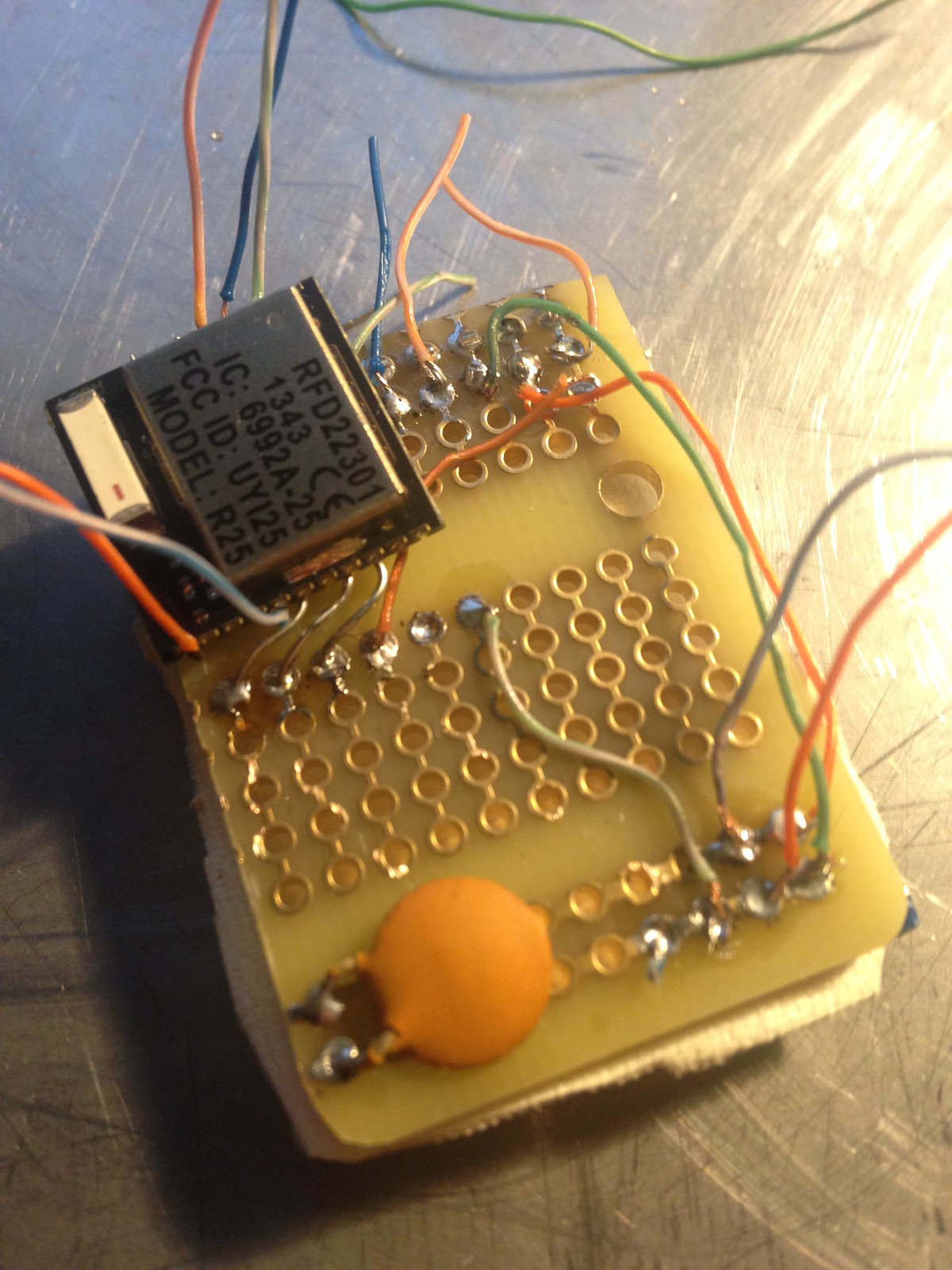
The first draft of thie prototype was… messy. I sat and thought about every connection, then soldered, then sat and thought some more. This is not a fast way to build a watch. This version of the setup worked, for a loose definition of ‘work’. I used really long jumper wires, and tried to pack them all together, so, of course, there were shorts. It also made the whole package considerably bigger than I thought it would be. So, kind of a dud.
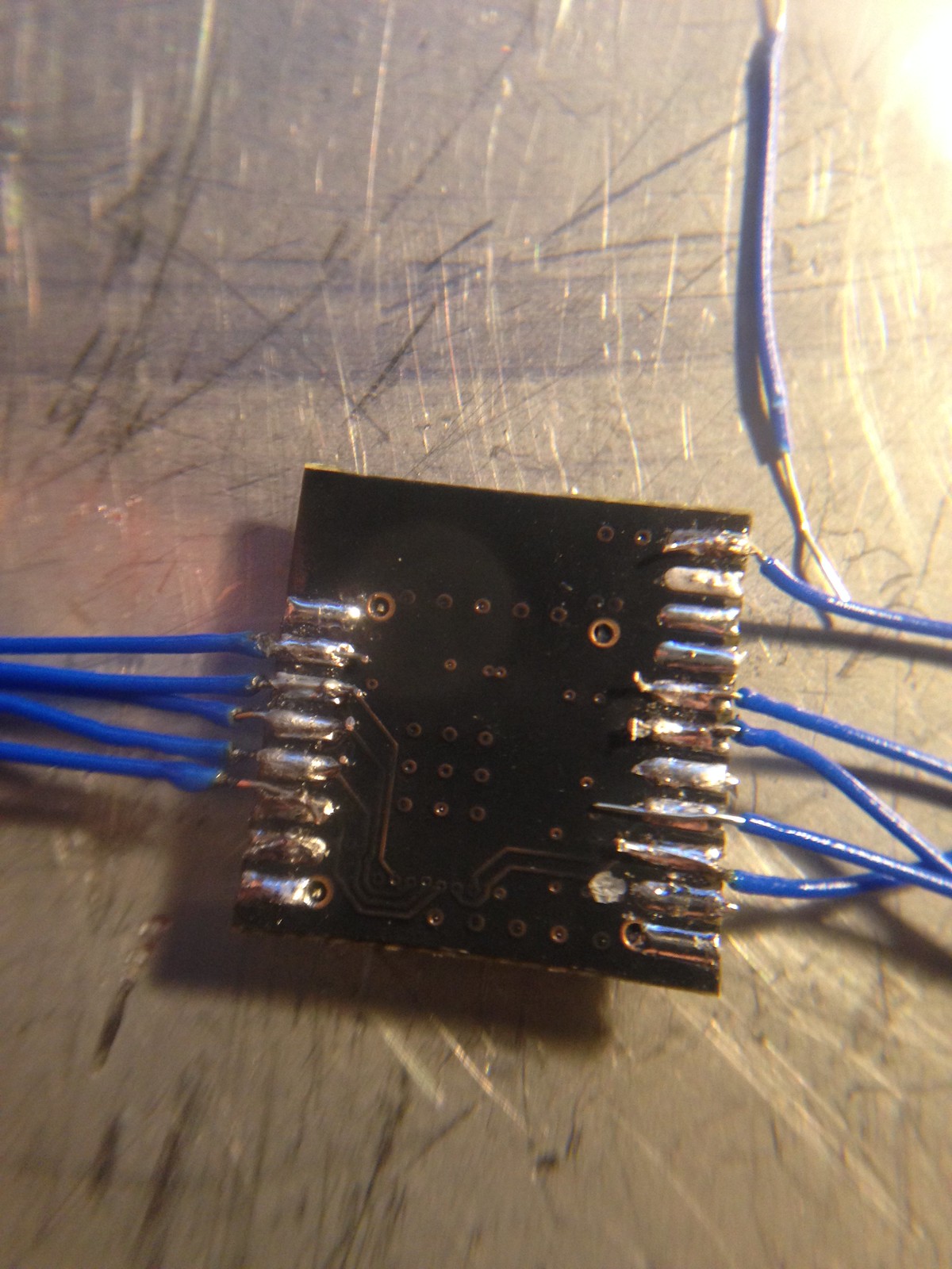
The second version was a little better; I shortened a bunch of wires, but the RFduino had a pad separation on the reset pin, which meant that it was kaput. I had bought 2 of them, luckily, so I wasn’t dead in the water. Not that the pad separation was my fault; these are SMT complonents, meant to be reflowed (soldered) once only. I knew I was pushing my luck, and it didn’t work out.
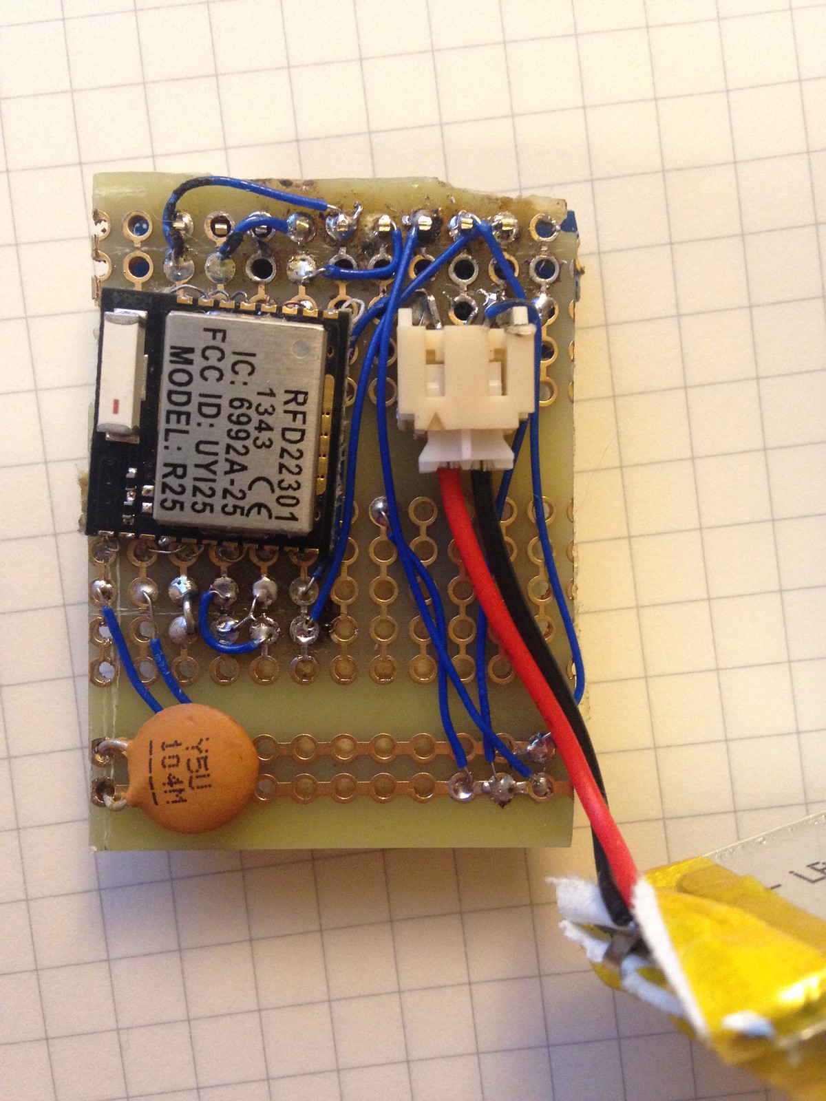
Version three I sort of took the experiences of the first two and combined them. I made the proto board a little longer, and soldered little legs to the rfduino, which I made out of wire wrap wire. They’re tiny, and a little flimsy, but in aggregate, give enough tension to hold the chip securely. I wired the power/programmer side so that I could plug it in directly and power everything off of it, for debugging purposes. You may notice, if you look closely, that Rx and Tx are switched from the circut diagram I posted in my last post; that’s because I screwed up drawing it.
So, what have I learned so far? There is a metric ton of information on how to do all of this stuff out there on the internet. If you have a question, someone else already has, and has posted on a forum about it, and been derided for being a noob. Then, someone knowledgeable will come along and actually answer the question, sometimes clearly, and sometimes in an offhand way that has you googleing again. Skim the trolling, look for answers. Then, there are the manufacturers’ data sheets, which are supposed to tell you everything you need to know to use their product. They give away perfectly good designs, so you get to benefit.

But seriously, solder braid really is magic. There’s more to say, and a ton more to do, but that’s enough for now.